text and drawings by Dave Roeder, MMR, photo by Richard Schumacher
Like many model railroaders, I have been around long enough to see quite a few layouts. There are also many different benchwork designs and track arrangements. The current trend seems to be the walk-in around the walls design. This is best from the access standpoint since it allows unlimited entrance/exit.
But there are also those who for various reasons do not want to loose the space required to turn trains around at each end of the entrance to a walk-in design. Most walk-in layouts have a return loop at each side of the entrance. The use of a duckunder is not a good solution. They limit access and are a hazard to tall folks.
A properly designed gate allows easy access without any drawbacks. The key to building a successful gate is in the design and construction. A good design takes into account not only access, but expansion/contraction, safety, and ease of maintenance. The gate on my HO scale Webster Groves and Fenton Railroad has all of these features. The design takes into account change due to temperature and humidity.
The features are as follows
 Hinges are standard interior 4 inch length with 4 wood screws in each plate.
- Door latch is a standard interior model with European style handicapped handles.
- Spring tension device is a bolt or roller type as used to remove play from screen doors or as used on sliding doors. This device pushes the door latch mechanism back against the flat side of the latch striker plate. These can be found at most hardware stores in the door hardware parts aisle.
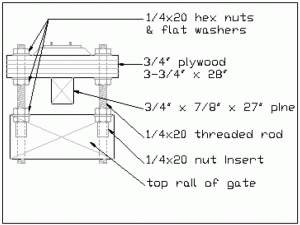
- Adjustable tee-girder roadbed made from ¾” plywood. For HO scale, the track roadbed is a piece cut to 3 ¾” X 28” which is strengthened by a piece of 3/4” X 7/8” X 27” long piece of white pine set on edge. This tee section is supported on four pieces of ¼-20 UNC threaded rod. These are set into the top rail of the gate using ¼-20 nut inserts of the type used for leveling legs on furniture. Flat washers and hex nuts are used to attach the roadbed section to the top rail. These four assemblies provide vertical adjustment for the tee section of roadbed. See figure 1.
- The adjustable track section provides adjustment of the gap between the latch end of the gate and the fixed track on the layout. This track section is made from an
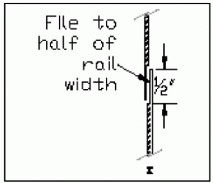
 Atlas re-railer / grade crossing which has been modified to allow ¼” lateral adjustment of the gap at the latch end of the gate. The Atlas re-railer is permanently attached to the layout on the fixed section of the layout using small wood screws. The section of the re-railer attached to the gate is also attached with four wood screws, but the holes in the rerailer for these four screws are slotted to allow plus or minus 1/8” lateral adjustment. On the gate end of the re-railer a 6” section of Atlas code 100 or code 83 flextrack is added. The ends of the rails are notched vertically 1/2” using a flat file. There must be one left hand and one right hand slip rail end on each rail to form the expansion joint. One end of the track has slip rail joints on the re-railer section. These mate with corresponding slip rail joints on the fixed track attached to the gate roadbed. See figure 2.
 - The track on the gate must be wired as a separate block. Wires dropped down from the fixed and the adjustable track sections will insure good performance and reliability. These wires must be routed through the hinge post with enough slack to permit the gate to be fully opened. Make sure the holes through the roadbed for the adjustable track section are elongated ½” to allow adjustment.
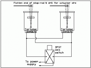
 Mechanical interlocks at each end of the fixed track work on the layout prevent accidental crashes off the end of the gate opening. These are made from Tortoise switch machines mounted horizontally. Power to operate these is provided through a DPDT limit switch mounted so as to be triggered by the closing or opening of the gate. The stop rods are made from coat hanger wire .062” diameter. One end is hammered flat for a distance of ¼”, then a .031”dia. Hole is drilled in the flat to clear the tortoise activating wire. I use .020” diameter music wire in the tortoise switch machines. A hole is also drilled through the roadbed in the center of two ties to clear the rod. Wire the switch machines to raise the rods when gate is open. See figure 3.
- General construction: The gate is made from 2 x 4 lumber for the frame.
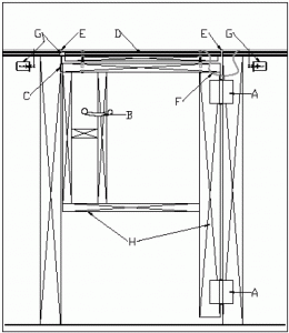
 The hinge post and latch post are 4 x 4 lumber. It is important to securely attach both posts to the floor. Concrete anchors or equivalent are required. Another solution is to place a 2 x 6 flat on the floor and attach it with liquid nails. The gate does not need to go all the way down to the floor. The bottom sill plate on the gate can be centered between the two hinges. This gives plenty of strength and still allows you to crawl under in the event that you need to get out with the gate closed. See figure 4 for general location of components keyed to these instructions.
One final note
This gate has been in use since 1995. I have adjusted the gap at the latch end about once a year. The leveling studs need attention about once a year as well. I added a de-humidifier to my basement after talking to a friend of mine and found it to be a good investment. The drier air eliminates seasonal humidity changes on the layout.


