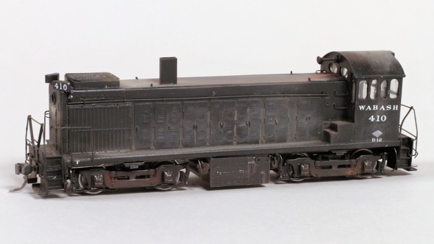
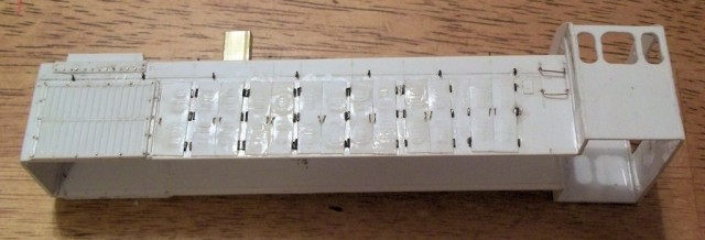
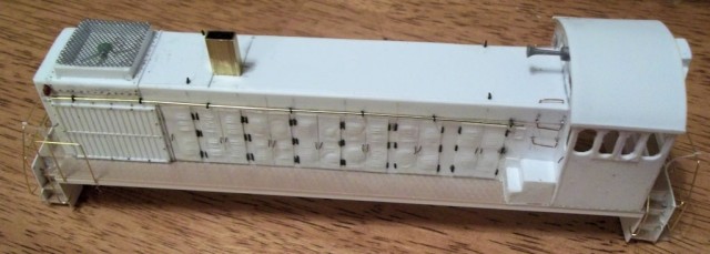
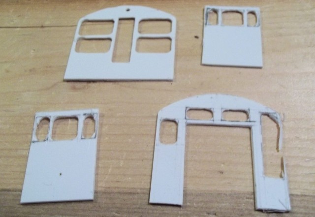
Finished engine photo by Richard Schumacher, Construction photos by John Carty
Lima Locomotive Works steadfastly refused to build diesels. As a result they were the last of the big three builders to enter the diesel market only doing so after a merger made them Lima-Hamilton. Although entering a superb series of switchers, it was too little too late. After merging with Baldwin to become Baldwin-Lima-Hamilton, Lima suffered the new company’s demise.
Models of the Lima-Hamilton switcher are rare. The Wabash carried about a dozen on their roster, so I looked for a way to obtain three: a single 1000-hp and a pair of 1200-hp. Since I cannot afford to buy brass models, I looked to build mine from scratch. The good news was that Kalmbach’s Model Railroad Encyclopedia Vol. 2 contained drawings. During construction I discovered the bad news that their drawing was incomplete (more on that later).
Since published drawings existed to “assist the hobbyist in building models,” I started with the drawings found in the Model Railroad Encyclopedia Vol. 2, Diesel Locomotives. I supplemented this with sketches during construction. I managed to obtain several Athearn blue box switchers of various kinds whose drives I intended to employ in my models.
I started by laying out the hood on 0.030” sheet styrene. I decided to place the roof and nose between the sides of the hood. Next I located positions for the hood access doors along each side. I also laid out the radiator shutters on 0.060” spaced clapboard siding. After cutting out the shutters, I framed then using 0.010” x 0.060” and 0.030” square strip styrene, using a piece of 0.020” x 0.040” strip styrene between the upper and lower shutters. The height of the shutters reflects the photos used, which is different from Kalmbach’s drawing (the first discrepancy I found). I cut all of the hood doors from 0.010” x 0.188” strip styrene except the ones nearest the radiators which I cut from 0.010” x 0.250” and embossed two sets of seven louvers onto each using a small screw driver aligned with a small square. I spaced each of the louvers 1/32” apart. After embossing them, I first glued the shutter assemblies and then the doors to each side of the hood. After assembly, while checking photographs, I discovered an error in door placement on the hood (the second discrepancy) which was minor enough that I left it be, but I will check photos more carefully next time. I also located and drilled holes for the grab irons at this time on each side of the hood. After checking motor clearance, I assembled the hood reinforcing the seams with 0.030” square styrene. After the cement dried, I rounded the corners with a file.
I added a panel to the roof for the radiator fan cut from 0.010” sheet styrene and then constructed the fan housing from 0.060” strip styrene. I added fan blades cut from 0.010” x 0.060” strip styrene to a piece of sprue for the fan. Using a #79 drill, I drilled holes in the radiator fan base and louver housings and inserted wire bolts (approximately 120 bolts). I then inserted wire handles to each of the hood doors bent from 0.010” wire (this is a lot easier than it sounds). I added Tichy lift rings to mount the side railings and to serve as lift rings for the hood. I also added Tichy drop and straight grab irons to the hood by the cab and installed wire through the lift rings to each side to serve as the side grab irons. I also added sand filler hatches near the cab and on the end of the hood cut from 0.010” x 0.080” strip styrene and drilled a shallow divot in each after the cement dried. I drilled a hole for 3/16” tubing into the end of the hood to house the headlight and added the end door cut from 0.010” x 0.250” strip styrene. Hinges were cut from the unused stems of the Tichy lift rings and set in place using liquid cement. The grab irons at the end of the hood were bent from wire. Marker lights were fabricated from the gates of a sprue from a Proto 2000 kit (I do not remember which one, but I think it was a Mather stock car). I cut the stack from brass tubing and installed it over a rectangular styrene peg mounted to the top of the hood.
I laid out the cab walls on 0.030” sheet styrene. I located the windows and doors and cut them out, filing the windows to shape. Next I cut out the cab walls. I assembled the cab being careful to keep the corners square. I laid out the doors on 0.010” sheet styrene. After cutting and shaping the window openings on the doors, I cut the doors out and installed them to the cab. I assembled the cab and then added it to the hood.
I cut out the deck from Plastruct tread plate sheet. I cut the pilots (end plate, inner step guards, and outer step guard) from 0.015” sheet styrene. I attached the end step guards to the bottom of the deck and then the end plate to the step guard and the end of the deck. I assembled the steps from the same tread plate as well as several sizes of strip styrene to achieve the correct step height, while also strengthening the structure. I added the inner step guards and trimmed them size. I added a piece of 0.040” x 0.060” strip styrene along each side of the deck between the inner step guards. I then added the foot boards to each end and added the hood and cab to the assembly. I drilled #79 holes for the grab irons and railing and bent them from 0.015” wire. The supports for the end railings I cut, twisted, and bent from 0.010” x 0.040” strip styrene. I added Details Associates cut levers using Details West eye bolts. The poling pockets were ears cut from Kadee coupler boxes.
I formed number boards for the cab by cutting and shaping two pieces of 0.125” square styrene. I drilled the opening for the headlight and added the lens retaining ring sliced from 3/16” styrene tubing. I added the sliding windows cut from 0.010” sheet styrene after drilling and filing the windows. I affixed the roof cut from 0.015” sheet styrene and the gutters from 0.010” x 0.040” strip. I formed the hood number boards from 1/8” square styrene filing them to shape.
I now reached the truly fun operation: the frame. I had previously built frames and floors for freight motors, road diesels, and interurban cars, but this marked the first time using Athearn switcher trucks. I laid out the frame on 0.060” sheet brass. I drilled holes in corners of the truck openings as well as at any point where the width of this opening changed. I cut out the frame using a hack saw and cut off wheels in my motor tool. I then cut out the center opening for the motor and trucks using the motor tool and cut off wheels again. When doing this be sure to use heavy duty cut off wheels or you will be replacing them constantly. Next I proceed to clean up the frame using files, holding the frame securely in my bench vise. This is a relatively simple operation requiring accuracy and patience. I test fitted everything regularly. I bent the motor cradle from 0.030” brass and soldered it in place. Next I soldered truck mounts for the Athearn switcher fabricated from 19/32” and 5/8” brass tubing. After the solder hardened, I cut away the excess tubing leaving enough on either side to hold the truck and added styrene mounting pads. These not only assisted in locating the trucks, but also helped to insulate the frame.
Next I added a styrene mounting pad inside the cradle and fabricated the fuel tanks and battery boxes from layers of sheet styrene. The fuel filters were sliced from 3/32” tubing and the sight glasses from 0.020” x 0.040” strip styrene. I added jacking pads to the frame using pieces of 0.040” x 0.188” strip styrene and 0.040” x 0.060” strip styrene. The air tanks were cut from 3/16” styrene tubing caped with 0.060” sheet styrene and filed to shape. Clearance for the motor was cut from each tank. I bent sanding pipes and air pipes from 0.020” wire.
After painting the body and frame assemblies with gloss black, I lettered the locomotive using Microscale Railraod Roman decals, printed builder’s plates printed on paper, and sealed them with Testor’s Dulcote. I added the window glass cut from DPM “glass” and windshield wipers bent from wire. I wired the drive train and led headlights adding a Digitrax decoder. Next I added couplers and assembled the hood to the frame. I weathered the locomotive with dry brushing and Bragdon Weathering Powders.
This completed the first of these switchers for my fleet.


I always enjoy the information you guys in the Gateway NMRA put out. I wish ya’ll were closer. Looking forward to you next train show. Thanks for all the info.
Kimball Kelsey
Paris, TN