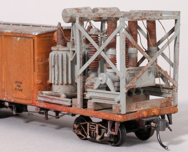
construction photos by John Carty, finished model photos by Richard Schumacher
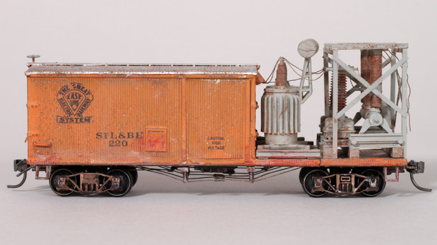
While reading a recent issue of the Flyer, (Volume 24, No. 2, Fall 2010) published by the Illinois Traction Historical Society, I came upon a photograph on page 5 of a mobile substation used by the Illinois Terminal Railroad in the article “Jackson ‘Jack’ Majors, The Last Living IT Lineman.” This car provided power to the overhead in order to keep trains running, while line crews conducted repairs to a substation or other power source. Since I model the East St. Louis & Suburban Railway System, another traction line, in HO scale, such a car provides a unique piece of maintenance of way equipment to model. Succumbing to temptation, I decided to kit bash my own car patterned after the prototype whose photograph appeared in the magazine.
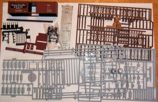
I started with a 36’ foot boxcar kit from Roundhouse. Using this kit in conjunction with an Atlas HO Substation Kit, I created a drawing of my version of the car in the magazine. The result is a composite design which captures the feel of the Illinois Terminal albeit in East St. Louis & Suburban form. With this in mind, I took the time to select components from the Atlas kit. I also sought to use as many of the components of each of the kits as possible.
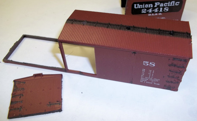
First I removed the cast grab irons, bolts, and brake platform from the body. Next, I plugged the mounting holes for the doors, and later the roof walk. I then cut the body twenty-two scale feet from the “B” end, retaining a strip of the body at the bottom with which to cover the floor casting. I also cut and saved the “A” end, saving the buffers, leaving this end about 0.040” short. After squaring the cuts, I installed the “A” end in its new location adding a piece of 0.040” square strip styrene to fill in at the bottom of the end. To this assembly, I filled the gaps with Squadron putty and dressed the seams. I also added two weather heads cut from 1/8” styrene tubing.
Next I drilled #79 holes and installed drop grab irons on the sides and “B” of the body, using a piece of 0.040” square styrene as a spacer. I also added to straight grab irons at the corner of the roof using the same spacer. I cut two pieces of the unused portion of the body to fill the door holes and filed them to fit, again filling gaps with putty. I also covered the vertical seams with 0.010” x 0.060” (roughly a scale 1 x 6) strip styrene. I replaced the bolts in the ends of the body with Tichy 7” hex nut/washer castings. Additionally, I added EMD louvers made by Cary on the sides and ends, and then framed them with .010” x 0.040” (roughly a scale 1 x 4) styrene. I also added Tichy brake parts to the “B” end of the car along with a brake staff cut from 0.012” brass wire. Next, I made a new roof walk from 0.010” x 0.060” strip styrene. I also replaced the end roof walk support I accidently removed earlier.
Moving to the floor of the car, I started by dressing the floor casting with a file. I also drilled out the holes for the truss rods, queen posts, and brake cylinder as well as to facilitate removing the flash from the stirrups. Given the sturdiness of the stirrups cast onto the floor, I chose to keep them intact. I affixed the queen posts with Zap a Gap and then added the train line in five segments. I installed the cylinder for the K brake from the boxcar kit, after drilling the lever end with a #79 drill, supporting one side with a small piece of 0.040” square strip styrene. Next I assembled Tichy brake levers to rods made from 0.012” brass wire. I cut a turnbuckle in half to form the clevis and added a short length of 0.012” wire. After creating the whole assembly, I glued the stem with the clevis into the hole in the brake cylinder. I next added truss rods cut and bent from 0.012” wire complete with turnbuckles from Tichy. I made certain that the end of the actuating rod lined up with the stirrup for the brake staff.
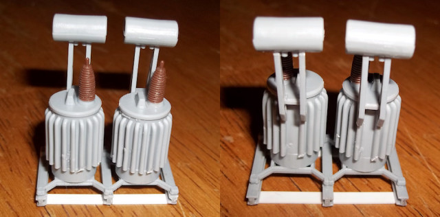
Moving now to the exposed electrical gear, I cut three pieces of 1/8” square styrene strip and two pieces of scale 2×12 to a length of an inch and a quarter or a scale nine and a quarter feet. Next, I assembled the two transformers from the substation kit per step 4 in the instructions. I made two changes at this point; first I used only three of the beams (part #31) and trimmed two of the feet on each of the parts #42 so that I could mount both transformers onto the three beams instead of the four specified in the instructions. I oriented the transformers so that the tabs on each of the caps faced parallel to the beams in the same direction and placed the assembly toward one end of the beams with the tabs pointing away from this end. The second change consisted of adding the pair of 2×12’s cut earlier as feet beneath the beams. I then completed step 9 in the instructions.
Next, I completed step 13 in the instructions. Next, I followed step 14 after shortening part #12 to a scale 9’ 3” by removing material inside of the cap on one end as well as the end with the protruding stud. I attached the stud near the end from which it was removed so that it projected from the same side as the mounting for part #13, the box for the control panel. I assembled the subassemblies from steps #13 and #14 per step #15 substituting the previously cut lengths of 1/8” square styrene for the supplied feet from the kit. I also shortened parts #34 to a length of six scale feet by removing material from the bottom. To this assembly I added a cage made from 0.060” x 0.060” styrene strips with 0.010” x 0.040” sway bracing. The cage measures 11 scale feet high by nine scale feet wide by 7 ½ scale feet deep. I painted the floor and electrical components grey and the car body orange (my maintenance of way color). I turned the floor over and painted the bottom black. The roof and brake wheel each received two coats of silver paint, while the deck received a coat of buff. Parts #34, #33, and #45 from the substation kit received a coat of oxide paint. Next I lettered the car body with a combination of custom made and Microscale decals affixing the decals with Champ Decal Set. I sealed the lettering with Testor’s Dull Cote.
I assembled the car substituting Kadee couplers for those supplied and replacing the wheels from the kit with metal wheel sets. After assembly, I weathered the car by dry brushing with acrylic paint and adding washes consisting of acrylic paint and alcohol. Next, I added wires cut from 0.010” wire to the weather heads before commencing assembly of the electrical components to the body of the car and then connected the wires to the different fixtures. I left three wires hanging from the “B” end to facilitate connecting the substation to the power grid.
Now the cars and motors keep running even while my maintenance of way crews carry out repairs to the overhead.

