text, photos and graphics by Richard Schumacher
presented as a clinic at the NorthStar 99 NMRA National Convention
this is the May 1999 original version
Modelers enjoy visiting and running on model railroads that are realistic in appearance and operated in a realistic manner. This only happens when the model echoes the mission of a real railroad — cars move to transport freight and passengers.
You’ll never start operations if you spend all your time planning. Start now with a method that works for your layout and add details and enhancements over time. The best way to develop the optimum operations design for your railroad is through the combination of practice and refinement.
Realistic Operation, Phase 1
The first step to realistic operations is to slow down. Run your trains at scale speeds. Place a yard stick next to a straight area of mainline and practice running at different scale speeds. The following table relates prototype speeds to the number of seconds it will take your train to move from one end of the yard stick to the other. Switching moves are usually performed around 5 mph. Movements within a yard are typically no more than 15 mph. Most mainline running is between 25 and 60 mph, depending upon era and type of train.
|
Time to travel 3 feet at scale speed
|
|||
|
Prototype Speed
|
N
|
HO
|
O
|
|
5 mph |
65 sec |
36 sec |
19 sec |
|
15 mph |
22 sec |
12 sec |
6½ sec |
|
25 mph |
13 sec |
7 sec |
3½ sec |
|
60 mph |
5½ sec |
3 sec |
1½ sec |
|
90 mph |
3½ sec |
2 sec |
1 sec |
Match scale speed running with prototypical starts and stops by accelerating and braking at scale rates. And never reverse an engine or train while it is moving.
Layout Design Impacts Operation
A primary goal in layout design is to create a railroad. The more it looks and works like a real railroad, the better for realistic operations.
Small layouts typically have one main feature, a single station or industrial complex. Medium sized layouts may have two or three main features, but work best if they are closely related. Large layouts may have many, including unrelated, main features. The length of your passing sidings determines the length of the trains you can run. The number of passing sidings determines the number of simultaneous trains you can run on the mainline.
The smaller the layout, the more important it is that operators can’t see the whole layout at one time. For a simple oval layout, with a town on each side of the benchwork, the addition of a scenic divider down the middle results in two immediate benefits: a) each town scene will immediately seem larger and b) operators will suddenly have the “feel” the railroad is going somewhere, that there is “distance” between the two towns.
The current Gateway Central project layout (a model railroad our Division designs, constructs, shows, and gives away at our train show each year) is only 5½’ x 6’ in size, but has imposing Walthers structures (paper mills and sawmill) and operation capabilities. This is practical only because there is a 4-foot wide scenic divider in the middle of the layout. Without the divider, the layout is a fancy loop of track, but with the divider it is a shortline connecting an industrial area centered on a paper mill complex with a rural area featuring a small sawmill. If you are interested, this layout is on display at the National Train Show.
Operations require clear and easy access to the track along with good operator visibility of the trains. This means that tracks need to be within reaching distance from an aisle, usually 30″ or less. Pop-up access doesn’t work for operations, walk-in or walk-around layout designs tend to work best. Operator aisles should be at least 28″ wide, with 30″ or 36″ preferable. Experience shows that the aisle needs to be slightly wider at the end of “blobs”, where the tracks make a 180º turn from one aisle to the next.
Walk-around control also works best for operations. Place the layout controls on the fascia near the portion of the layout they control. Avoid placing the throttles at a fixed location, even if it is “in the middle of everything”. Radio and IR throttles are now available for operators who hate trying to find (and figure out) a plug-in point.
Railroad height effects visibility and reaching distance. Low benchwork offers a “birds-eye” overall view and a deep reaching distance. It is easy to reach in 36″ on benchwork only 36″ tall. High benchwork provides a detailed look at the cars and rolling stock, and makes you feel more part of the local action. However, on benchwork 50″ high, you may only be able to reach in 20-24″. You may also have problems determining which way that switch on the back track is thrown. However, high benchwork is significantly easier to work under for maintenance. The current trend is towards “eye-level” modeling, with track height at 52″ or more.
Good operator visibility means you need to avoid long tunnels. It is most reassuring to operators if they can see some part of their train at all times. A rule of thumb is that as the caboose disappears into the portal, the engine of that train should be emerging from the other end of the tunnel.
Double decking is an option for medium to moderately large layout spaces to increase the length of the main line run or to add a significant branchline. Make sure you have enough separation between the levels to build respectable scenery and see the trains. Usually at least 14″ open space between the levels is required (with 16-18″ preferred). Also, don’t stick a helix in the operational portion of any route. Having a train disappear for multiple minutes inside a hidden spiral only irritates, confuses, and distracts crews from the operations. Helixes, if needed, should only be placed at the end of runs.
Design in a way to keep a train running continuously without operator intervention for public displays or train shows. The public (or relatives) usually are interested in only two things when they visit a railroad: a) where there trains running? and b) could I recognize some scene or industry on the layout? Such a continuous loop is also useful for breaking-in and testing engines and rolling stock.
Single track is much more interesting than double track. Unless there is an absolute need to model double track (because you have to keep a train running constantly, or because double track is a key feature of the prototype railroad you are modeling), design your railroad as single track. This is especially important on small layouts where the space can be better used for on-line industry spurs or station features. Even on large layouts, use multiple track only where it adds to operation capabilities.
Medium and large size layouts allow the construction of a true point-to-point scheme. For many modelers, the first design concept for applying this scheme uses a significant yard at each end of the line. Unless your focus is yards or terminals, care needs to be taken that these features don’t eat most of the layout room space and budget. If your primary interest is in terminals, it is usually best to model one large terminal, and let the rest of the layout act as “staging” for trains arriving and departing the terminal. Most modelers will find it best, in terms of cost and maintenance, to feed only one major yard or terminal on their layout. This is also an application of one of the John Armstrong layout design principles, “Don’t do the same thing twice.”
Four design and operating concepts may be applied to a one major terminal model railroad:
- Out and back
- : The train leaves the terminal and proceeds around a line which ends up back at the terminal. The one terminal may be operated as if it were two different terminals, one at each end of the line. The scheme works best of the four for small spaces.
- Division point
- : Trains proceed to staging in each direction out of the terminal. The terminal is a “division point yard” where all trains stop and crews are changed. This requires a reasonable mainline run on each side of the yard before going into staging. This scheme typically works best in large spaces, and is especially suited for railroads where mainline running is the operations goal.
- Main terminal
- : One end of the terminal immediately plunges into staging, the other end connects to the mainline run portion of the layout before going into its own staging. This scheme works especially well for combination mainline run/switching oriented operators.
- Branchline
- : The terminal is on a mainline “oval loop”, the other part of the oval is hidden staging for mainline trains. A branchline connects to the main at the terminal, and meanders off into the countryside servicing local industries. Mainline trains drop off and pickup cars for the branchline, left at the interchange terminal. Obviously a switching-oriented design.
Yards are supposed to be operated, not to act as storage. The goal of a real yardmaster is to get as many cars as possible out of the yard. Large yards make up trains heading for other yards. Small yards sort cars destined for local industries. The only real yards that store cars are passenger yards. Make the aisle a little wider near main yards, and design in a place for the yardmaster to sort his paperwork. And you’ll never get your yard to work right if it hasn’t got a separate lead that’s as long as the longest yard track.
Industrial switching areas may be located near yards or somewhere “down the line.” Real railroads try to make industrial trackage as simple as possible, so avoid the impulse to design a “switching puzzle” into your layout. Most railroads encouraged development of industrial sites in the immediate area surrounding small town stations. A passing siding at a town typically had a couple industrial spurs attached.
As the size of the layout increases, so must the quality of the construction. Model operations require the entire layout to be more reliable than what is required to just run trains. The quality of the construction must be such that the size of the layout does not exceed the maintenance (time and cost) budget of the owner.
The Concept
Transform your model railroad into a real rail transportation system. Your design concept establishes where it is located, the era, which towns are served, connecting lines, and traffic patterns. The concept needs to match the model — the size of the layout and the access considerations will determine whether you can model an entire railroad, a division, a couple of mainline towns, or a minor station along a branchline.
Geographic area, era, and transportation needs results in a concept of where, when and why the railroad exists.
The geographic location (or setting), along with the era (or timeframe), selected for the layout will effect both the scenery and the traffic. Just as you won’t find many high volume commuter lines in a snow-covered mountain range, it is equally unlikely to operate a gold mine in the middle of flat farmland. Realism of the layout is enhanced when all of the items (industries, rolling stock, structures, traffic patterns and volume, signs, vehicles, etc.) in the scene are of the same era. If you select to model a specific prototype, recreating the location and traffic of that prototype at a specific point in history will ensure an appropriate match. If you freelance a railroad, it’s best to pattern your location, scenery and traffic on your favorite prototype railroads in a specific era. If you are unsure of what era to model, its usually best to create the scenery to match the earlier era you prefer, as it may always be modernized later. Club layouts are usually based on local railroads, since the local roads and scenery are more likely of interest to current and prospective members, as well as visitors.
For freelance railroads, developing a “history” can advance the railroad concept. Explain its location, traffic patterns, and method of operation.
If station names are based on real towns in appropriate sequence, they not only add to the realism, but also place the railroad geographically. Since real cities are typically too large to model, those stations either become hidden staging, or are modeled as a station or yard on the edge of the city but using a specific recognizable local name. Chuck Hitchcock did this with his Argentine depot, since Kansas City Union Station would have been too large to appropriately model. The St. Louis Southern terminates at Gateway Yard near Broadway Station as there is no reasonable way to model the Mill Creek Valley yards and St. Louis Union Station (unless you really want to build two triple track interlaced wyes feeding 32 tracks under a five-span train shed, of course).
At one time it was popular to name towns in alphabetical order, supposedly giving the operators a “clue” as to the sequence of the stations. In reality this doesn’t assist novice operators (who may not figure out they are in alphabetical order anyway) or your experienced operators (since they will know the actual sequence and do not need this “help”). It is much better to select station names appropriate to what is being modeled, and then give each operator a list showing the station sequence.
Realistic Operation, Phase 2
Name everything on the layout. Even if the oil refinery is only a can of Pennzoil sitting next to the siding, name the refinery and the town where it is located. The same goes for the flour mill (empty Saltines box) down the line. Now you are delivering low-sulphur coal from the Whitney mine to the Banholzer Steel mill, and not just moving cars from “here” to “there”.
This change has two immediate effects. First, your operators are now transporting freight between actual destinations, not just moving cars around. Secondly, it is an initial preparation step to later add a car forwarding system.
Most industries are large enough to have multiple freight docks or doors. Each of these is either numbered or labeled on the real buildings, since deliveries not only have to be made to the right company, but also to the right dock door at the company. Your operators will need to deliver lumber to the shop’s dock door and boxcars for the finished furniture to the shipping dock door.
Name your railroad as well. If you are modeling a specific prototype, this is easy. If you like a prototype, but want to create your own route, follow the prototype but make your own division. The Ozarks Division of the Missouri Pacific won’t be found in any timetable, except for the ones in Bob Amsler’s basement. There you will be surrounded by standard MoPac engines, rolling stock and lineside structures, but in the rolling mountains of the Ozarks.
Modeling a specific prototype railroad has become very popular in recent years. It also provides an instant guide to scenery, rolling stock, structures and operations. But it also limits you to the specific engines, cars, and traffic patterns of that prototype. Historically, freelance railroads were more popular, perhaps because of the limited number of prototype-specific models that were available, or because of the difficulty in obtaining prototype specific information. Still, there are some modelers who rather create their own alternate version of history.
Creating a freelance railroad requires even more attention to railroad concept. You need a concept, and railroad name, which has a solid basis in the area you are modeling, as well as a prototype “sound”. Allen McClelland’s Virginian & Ohio has an excellent prototype-like concept, modeled location, and name — but is a freelance railroad. Make sure your name matches the concept: the El Dorado & El Reno sounds like a small connecting line, the St. Louis Southern sounds like a Cotton Belt or MoPac regional competitor, and you would expect to find the Utah Belt in the southwest. Multiple interchange connections to real railroads will improve the realism and operating possibilities of your freelance railroad.
When creating a color scheme for a freelance railroad, keep in mind Paul Mallery’s four guidelines: 1) easy to apply, 2) realistic, 3) distinctive, and 4) pleasing. And when you have custom decals made, make sure you are using an era-appropriate type style and don’t over-size the lettering.
Most locomotives, cabooses, and passenger cars (pre Amtrak, of course) would belong to the modeled railroad. Repainting this rolling stock to the home road is another significant step to increasing realism during operations.
Oh, by the way, now that you’ve named everything, put those names on the model railroad! Towers, junctions and towns get name signs on the fascia at their location. Each building needs a sign with the company name. This way, your operators will know where they are, or be able to find their way to where they are supposed to be. Really helpful owners will place a track diagram of each town on the fascia by that town, with all of the sidings labeled. Regularly spaced direction signs (indicating which way is “east” and “west”) also work to minimize confusion.
Interchange
An important traffic source for almost all railroads is interchange (transferring freight cars between railroads or lines of the same railroad). Even the Alaska Railroad receives foreign-road cars via a car float. Interchange traffic is especially useful when designing operations, as almost any type of car, in any quantity, may participate in interchange operations.
Local interchange occurs when cars are set out to be picked up by another train of the same railroad. This means each car has a destination, usually on the modeled portion of the railroad, beyond the interchange point. A through freight drops off cars at a station for setout by the local drill.
Such interchange may also be simulated, where the interchange is the actual destination on the model railroad. Operations here usually assume that the cars were picked up by the foreign road and then returned, now with a new destination.
Foreign road interchange is typically modeled by one or more tracks leading to the (non-existing) other railroad. Larger interchanges look like small yards. A car float makes a very interesting kind of interchange point, significantly easier to model (in HO) with Walther’s new waterfront kits.
If you actually have the space to model more than one railroad, the interchange traffic between the two railroads will be an extremely important part of the operation design.
Who Does What
Real railroads are a perfect example of teamwork. Each operation is carried out by many individuals performing specific tasks in cooperation. Many jobs on prototype railroads aren’t typically modeled. The jobs modeled are usually limited to those directly involved with moving cars and trains. In many cases multiple real jobs are combined for modeled jobs. For instance, one model operator will usually wear the “hats” of fireman, brakeman and conductor simultaneously while another operator is engineer.
The train crew runs one train. On modern railroads, the train crew consists of an engineer (drives the locomotive), conductor (in charge of the train), and brakeman (assists the conductor). During the steam era, there was also a fireman in the cab and at least two brakemen. The head brakeman rode in the locomotive while the flagman, or rear brakeman, rode the caboose with the conductor.
If you are modeling a short line, the train crew may be all there is to your modeled operations. If your railroad runs multiple trains, they usually come from somewhere, and that is usually a yard. If the yard is large enough to have its own switching locomotive, that locomotive will have a yard drill (an engineer, conductor and brakemen). The yardmaster directs the yard drills, and is responsible for making up and breaking up trains. Switchmen assist the yardmaster in larger yards. Small yards may have a freight agent instead of a yardmaster.
Once you are running all those trains, you’ll need a hostler to operate and prepare locomotives between the engine facility and yard. The power desk or roundhouse foreman makes sure appropriate motive power is assigned, available and ready.
Dispatchers
control the movement of trains on mainlines. During the steam era, dispatchers directed towermen at interlockings and block operators at stations without interlockings. Dispatchers communicate directly with train crews today.
Trainmasters
are locally responsible for the operation of the railroad, including supervision of dispatchers, yardmasters, and train crews. The rules examiner makes sure everyone knows the operating rules of the railroad.
The superintendent is in charge of a railroad division. Large railroads had multiple superintendents managed by a general superintendent.
So how to you model all this?
Model Layout Crews
Most model railroads use either one- or two-man train crews. Two-man crews have an engineer who runs the locomotive and a conductor/brakeman who manages the waybills and throws switches.
Small yards may be switched by visiting train crews. A mid-sized yard will have a yardmaster, who typically also operates the yard drill. Model layouts with very large yards, especially those with multiple yard drills, will have separate operators for each drill with a yardmaster in charge. If there are a large number of engine facility movements required, a model railroad may have the need for a hostler, especially if all of the movements for steam locomotives are modeled. Otherwise, the yardmaster will also as act as hostler.
Older model railroads were designed with fixed engineer throttle locations, for large clubs these were usually located on an elevated platform in the hope of seeing the trains. Since it was difficult to switch and uncouple cars from 50 feet away, the conductor/brakeman would walk with the train, giving hand signals to the engineer, and throwing switches. These larger layouts also had towermen who would operate complex interlockings and report passing trains to the dispatcher.
Most new model railroads are designed with walk-around throttles, so train crews follow their trains around the layout. The conductor/brakeman usually throws all switches along the route, except for those controlled by a dispatcher with CTC (Centralized Traffic Control), which may be thought of as an interlocking machine for a large section of railroad. Adding CTC to a model railroad is a significant (time and cost) project, and is only usual for Class 1 railroads.
The dispatcher is best located where he cannot see the model railroad. The dispatcher tracks the movement of trains on a train sheet and issues orders to keep them rolling.
The dispatcher receives information from the towers and station operators (which may be modeled as called in reports from train crews when they reach towers and stations) and issues train orders back to the crews. This is usually modeled with phones at station locations (steam era layouts) or radios (modern era). If you have CTC installed, the dispatcher directly controls mainline switches and signals with the CTC machine. The location of trains is displayed on a CTC machine by the indication of occupied track sections. The dispatcher controls trains by setting signals and throwing switches. With CTC, there is less communication between the trains crews and dispatcher as towers and crews don’t have to report in with their locations.
Model railroads also need a superintendent to prepare the rule book and timetables, qualify and orient operators, oversee the operating session, and investigate and resolve problems. Of special importance is ensuring that operators know how to uncouple and handle cars without damaging the coupler or car.
Realistic Operation, Phase 3
Get the railroad to work! Nothing ruins an operating session faster that engines which won’t run and cars that won’t stay on the track.
Locomotives need to run smoothly and reliably. The couplers on engines must also work every time and be the exact correct height. Power which doesn’t meet these standards needs to leave the railroad until they can be repaired.
The trackwork and rolling stock need to work together. Ignoring derailments caused by klutzy operators (hopefully they’ll improve with practice), 2 derailments or less for every 100 car moves is your performance goal. Checking track gauge, tuning turnouts, testing wheelset gauge, adjusting coupler height, and weighting cars correctly will all add up to better operations. Cars with problems (constantly derail, coupler problems, weight problems) need to be banished to the RIP track until they can be repaired.
An operating session will be much more fun with fewer cars and locomotives that all run properly, over a session with more rolling stock that won’t roll.
Your electrical and control system is the other side of the coin for getting good locomotive performance. If your control panels require a computer network administrator to understand them, they are distracting from the operations. Your goals here are a track power system that works reliably and is very simple for operators to understand. My recommendation is to go out and purchase a DCC system now.
Which DCC system you purchase will depend on what you like in throttles, and perhaps which DCC system your operators have purchased for their home layouts. Although DCC decoders (the part you put in the engines) are compatible between brands, the throttles are not. Model Railroader published a nice overview of the available systems in their June 1999 issue. After you decide on the brand, one way to reduce the throttle cost is by purchasing their “advanced” throttles for the yardmaster & hostler and “intermediate” throttles for road crews.
DCC will allow you to get your railroad “up and running” quicker than the installation of conventional block control. It allows multiple trains to operate without needing to consider the location of power gaps, or the proximity of engines to each other. This immediately makes operations that are difficult with block control, such as helper districts, multiple switching crews in the same yard, and consisting multiple unit diesel lash-ups, simple and easy.
Don’t overlook the fact that DCC eliminates the need to perform the non-prototypical, and confusing to some operators, task of throwing control panel switches to assign power to track blocks. It can also simplify and automate reverse-loop wiring and operation. You can turn on and off engine headlights, ditch lights, gyralites, and strobes from the throttle. And you may reprogram the running speed characteristics to make different brand engines run well together.
If you are serious about multi-train operations, the simplicity of use and freedom of engine movements more than outweigh any perceived additional cost of using DCC over conventional control systems.
A personal warning
: the purchase of a Soundtraxx DCC digital sound decoder for a steam engine quickly leads you on the road to addiction. You’ll want a sound decoder in each of your steam engines. You’ll start using whistle signals all the time. And you’ll wish you had purchased a North Coast or Wangrow DCC system so you have a separate button on your throttle for each sound the engine can make.
Timetables, Part 1
Employee timetables
and rule books govern the operation of the railroad. Rule books establish the rights and obligations of trains and crews, especially for unsignaled areas (like most model railroads). All railroads operated by the Standard Code rules until the mid-eighties. After that time, each railroad modified the rules to fit their communications needs, but kept their Standard Code number and basic concepts.
The schedule is the part of the employee timetable which list the class, direction, frequency, number, and times at specific locations (like stations and towers) of each regular (meaning scheduled) train. Modern railroading has eliminated class and schedule timings.
Regular passenger trains were usually listed as 1st Class trains. Freight trains were typically 2nd (or lower) Class, although a very few special freight trains were also 1st Class. Trains not on the schedule are extras.
Regular trains are identified by number (#17) and sometimes by name (the “Super Chief“). Generally, on east-west railroads, westbound trains have odd numbers while eastbound trains have the next higher even number. For north-south roads, odd numbers are southbound with northbound as even. Passenger trains typically have low numbers while freights are given higher numbers.
Prototype schedules are in table format. Typically eastbound trains are listed in one table (usually read down the page for station sequence) while westbound trains are in another table (usually read up the page). If there are few trains on the schedule, it may be formatted as one table with the station names in the center, eastbound trains listed on the left side (read down), and westbound trains listed on the right side (read up).
Special symbols, indicated on schedules as letter codes next to each station, explain other facilities available at that location. Common symbols include:
| A | Arrive |
| L | Leave |
| S | Station Stop |
| F | Stop on Signal |
| B or Q | Telephone (or Radio) booth |
| D or LS | Operator on duty during daytime |
| N or CS | Operator on duty 24 hours |
| C | Coal |
| O | Fuel Oil |
| W | Water |
| D | Diesel Fuel |
The problem with the prototype schedule arrangement for model operations is that it is hard for model operators to quickly determine the locations of meets and with which trains. This might be the first time an operator is running that train. Real distance between stations is shorter, and traffic density is much higher than on real railroads – so the action happens much faster. The best solution is to make single-train schedules. These list the stops for that specific train, and indicate meets with other trains.
An employee timetable will go into great detail concerning speed, track limitations, and equipment restrictions by train, route, service, weight, type of movement, specific locations, and equipment class. These vary from railroad to railroad, and division to division. For modelers, speed restrictions by train and route are most practical (and most likely to be followed for the operators). Simple restrictions like 45mph for freight, 65mph for passenger, 25mph within yard limits, 15mph on the Riceland branch, and “don’t take engines out on the car float” will add operating interest and realism without being overly complex.
Movements within yard limits may be made without timetable or train order authorization. Yard rules allow engineers to proceed when they see the track is clear, but not over 25mph, and not outside the yard limits. Movements within the yard are directed by the yardmaster.
Right, Class and Direction
Right
, Class, and Direction are the three ways one train may be superior to another (on single track). Right is granted with a train order. Train order right always supersedes superiority by timetable.
Class
and Direction are listed on the schedule. A train is superior to trains of a lower class. Regular (scheduled) trains are superior to extras. For trains of the same class, direction will indicate which is superior. The superior direction will be listed in the timetable.
The inferior train takes the siding at meets. If an inferior train is running late, it is responsible for making sure it is in the clear for superior trains. When a superior train is late, it “owns the road” up to the point where the schedule says it should be. In this way meeting points are adjusted when regular (scheduled) trains are late.
Realistic Operation, Phase 4
Develop a sequence timetable from a train service plan. The plan begins with a vertical list of the sequence of towns along your route. Individual trains are added as adjoining columns, showing where they originate, terminate, turn, set out blocks of cars, or switch. Typically a line represents the run of a train, with symbols (such as a filled box for switching, or an empty box for block moves) on the train line indicating towns it works. The ends of the line indicate the start and end points of that train’s run.
This is similar to timetables, which are also based on a list of stations and towers. On timetables, trains are grouped by class across the top, and listed in order of their departure within each class grouping. A main difference is our initial train service plan isn’t concerned with time-based scheduling, only what trains are running where.
Appropriate passenger and fast freight service connects major cities. Blocks of cars are setout or picked up at mid-sized towns by through freights. Each town on the line needs to be served by one train that switches the local industries — either a way freight, turn or local. Applying these guidelines, create a basic train service plan for your railroad.
The following suggested train categories and train number ranges may be used as a starting point for designing your initial train service plan.
- First Class Passenger Service, #1-20, combination of higher-speed “limited” service with few stops, and slower local service of every town.
- Second Class Fast Freight and Express, #21-48, these run nonstop except for crew changes. Steam era reefer express trains also had to periodically stop at icing platforms.
- Second Class Manifest or Through freights, #51-98, provide fast service between major yards. They drop off blocks of cars for locals to spot at industry sidings, and pickup blocks of cars headed in the direction of the through freight that locals have pulled from sidings. Sweeper trains may run daily each way on the line to ensure all blocks of freight are collected and moved in a timely manner. Customers usually want their cars delivered early in the morning and collected in the evening.
- Third Class Way freights (aka Peddlers), #101-148, perform local switching, usually between two local yards. It may also pickup and setout blocks of cars for locals, especially at towns with major railroad customers. A variation is the turn, which leaves a yard, runs to a specific town on its route, and then returns to its home yard. The turn switches the towns along its route in both directions. Other variations are a coal drag (which may be a slow version of a through train), or an interchange turn, which moves cuts of cars between a yard and a connection to another railroad.
- Third or Fourth Class Local freights, #151-198, perform local switching over smaller areas, usually concentrating on the needs of one or two major online customers. It also works blocks of cars left by other trains.
Trains which move from one interchange to another is bridge traffic. The locomotive and caboose may be exchanged for home road equipment for this movement, or the foreign road equipment may stay on representing running under trackage rights or as pool service. This is a simple way to explain another railroad’s equipment running on your layout.
Now that you have a train service plan, write an instruction card for each train. This describes the “action”, what that train does and where. This card lists each stop, and the type of work the train performs at each location.
Then, pick which direction is superior on your railroad. Typically, it is selected so as to move priority traffic into a major commerce center the quickest.
Finally, arrange the train instruction cards in the order in which the trains will be run. This arrangement is a sequence timetable. You are now ready to start an operating session.
The first crew runs the first train. Each additional crew runs the next train instruction card in order. As a train completes its run, that crew then selects and runs the train on the next available instruction card. Meets are handled using the rules of class and direction. Inferior trains need to clear the way for superior trains.
Your first operating sessions may be limited to only first and second class trains. As your operators gain experience, add the third and fourth class traffic. Your experiences will quickly show where the sequence of running the trains will need to be changed, or trains which simply “don’t work” and have to be eliminated or modified.
The whole idea of walk-around layout design and control is for the crew to stay with their train. Make sure your crews keep with their trains.
Hidden Staging
Staging
provides a place for trains to originate or terminate off the modeled layout, it represents “the rest of the world”. Staging may represent other divisions of the modeled railroad, or connecting railroads. You may have multiple staging yards. Staging provides a pool of complete trains, ready to run onto or across your layout.
Generous staging should be designed into the layout from the start, as you’ll always wish you had more or longer staging. You need at least one more staging track than the number of trains you plan to stage, and staging tracks should be longer than your longest train. Continuous staging is better than stub-end staging, since you don’t have to turn trains (or the worst case, back them over the entire layout to their original staging location).
Since staging tracks are frequently semi-hidden, or at least somewhat out-of-the-way, design them to operate as reliably as possible. This means use #6 or larger turnouts, avoid any reverse curves, and perhaps install a rerailer at the end of each track (I first saw this trick on the Virginian & Ohio). Make sure you can easily see and reach staging tracks to rerail cars. Staging may be so busy it requires its own operator, usually called a staging dispatcher.
Realistic Operation, Phase 5
Now that we have a sequence of trains running, let’s give the local and way freights something to do. It’s best to practice switching before trying to implement a full waybill or switchlist based car-forwarding system. You may even prefer one of these low-paperwork methods.
Switching cars at industries simulates the movement of freight traffic. Train crews are kept busy if they are switching between 20-25 cars per hour. The two basic systems presented in this section do not have complex paperwork, and do not cause problems when cars are misrouted, switching isn’t performed at a location, or paperwork misplaced.
When operating, always ask about the railroad’s policy before touching any cars or locomotives. This is especially true of engines and when derailments occur. And make sure you know the correct way to uncouple cars on that railroad.
It usually works best to make the pickups before the setouts.
And throw hand-throw switches gently. Some mainline and passing siding switches may be remote controlled by a tower or dispatcher. Check the route before throwing any switch to make sure you are throwing the correct one. And make sure all of the switches are set back to their correct position when you leave that town.
Whit Tower’s proposed the “thinking man’s” car-forwarding system. This approach believes “it really doesn’t matter where or how a particular car is spotted.” The train instruction card simply adds the quantity of cars to be switched at each town. The crew simply decides which cars they want to switch at what industry. The one rule with this method is to pick up one car for each one setout.
The wheel report car-forwarding method uses one form. The first column of the form is the towns in sequence. There is an additional column for each car type on your railroad. You may use AAR car codes, or common descriptions like “boxcar”, “hopper”, “gondola”, “tank car”, and “flatcar”. A final column is used to compute totals. The train number, and the version number (1, 2, 3, etc.) of the wheel report form for that train, is written at the top of the form.
Using the train instruction card you created for sequence scheduling, determine the towns this train switches. For each town, determine how many cars of which types you want to switch there. For instance, you may decide to switch two boxcars and one tank car at Camden. On the Camden line, you would place a “2” in the boxcar column, and a “1” in the tank car column. The last column, the totals column, would get a “3”.
When you have completed this for each town serviced by that train, compute the final total (add up the total column). This is the number of cars that will be placed in this train.
The yardmaster uses the wheel report to put together a train. Any car in the yard may be used with the system, as long as it is the right type (“boxcar”, “hopper”, etc.) as requested on the wheel report. Real railroads block trains to make switching easier. Blocking is simply grouping together cars with the same destination. The yardmaster groups together the cars for each town to be switched. The block of cars immediately behind the engine are for the first town, the second block is for the second town, and so on. Through cars may be added at the end if you want to lengthen the train.
An engine and caboose are added, and the crew starts their run. The train instruction card describes their run. The wheel report tells them how many cars of what types are switched at each town. The actual switching performed at each town is at the pleasure of the train crew. Advanced operators will try difficult switching moves; new operators may go with easier moves. Usually each town only has a couple of locations that may reasonably accept specific car types. Again, the main rule with this method is to pick up one car for each one setout. This way, the number of cars spread across the layout in industrial sidings is kept constant.
When the train terminates its run in the yard, its cars become “fair game” to use to assemble another train.
You may further enhance operations by surveying your industries. At each town, you’ll want to collect each industry’s name, its siding capacity, what it ships and in what kind of cars, and what it receives and in what kind of cars. To add to the “real railroad” feel, you may want to use AAR car designations.
Example AAR car designations found in the Official Railway Equipment Register. The NMRA recently reprinted the January 1953 ORER.
| Boxcar, standard | XM |
| Boxcar, automobile | XA |
| Refrigerator, ice bunker | RS |
| Refrigerator, mechanical | RP |
| Insulated boxcar | RBL |
| Covered hopper | LO |
| Hopper, twin | HM |
| Hopper, triple or quad | HT |
| Gondola, mill | GB |
| Gondola, gravel | GS |
| Ore car | O |
| Tank car | T |
| Flat car, general use | FM |
| Flat car, carrying trucks/trailers | FC |
| Pulpwood car | LP |
| Stock car, cattle single deck | SM |
| Stock car, poultry double deck | SP |
| Caboose | NE |
Use this information to enhance the track diagram of each town. Indicate the specific car types that may be spotted at each dock door of each industry. Since only appropriate cars may now be delivered at that industry, the challenge of operation, and realism of the switching, is increased.
Usually a final switching rule is added: if you move a car to switch another car, you need to put the first car back where you found it.
Timetables, Part 2
Your sequence timetables may be converted to a time-based train schedule. Until recently, the easiest way to construct a time-based schedule was graphically. On train graphs, time is plotted against distance. Stations are fixed locations on the distance axis. Trains are represented as lines, and meets occur where lines intersect. The slope of the lines on the graph corresponded to the speed of that run segment.
The easiest way to create a schedule today is to use scheduling software. Even if you don’t own a computer, it is still easier to find one to use to create your schedules. DPS Train Scheduler http://home.earthlink.net/~dpssys/Software/software.html has a significant advantage for this application because it is available free from their web site. Albion sells their ShipIt! Scheduler http://www.penn.com/albion/html/scheduler.html, which has some additional capabilities over the DPS product, for $49.95.
Fundamentally, scheduling software takes the sequential list of your towns, and their distance from one end of your railroad, and adds trains moving at selected speeds, making stops of specific duration. The software generates a train graph and schedule from this information.
The NorthStar 99 clinic presentation, and the expanded version of this article, will include a step-by-step description of how to create a train graph using both the software and manual methods, and convert it into a model railroad timetable and scheduled train instruction cards.
When designing a model timetable, keep the following additional guidelines in mind:
- Times shown on timetables are usually departures, except for the time at the last stop.
- Meets and passes are indicated by times in bold type, with the number of the other train usually noted next to the time.
- The timetable is a great place to list special instructions for the operators, explanations on how to use confusing control panels, and standard hand signals or other communications protocols.
Realistic Operation, Phase 6
Since the model passengers and freight consignees are not going to complain about poor service, the use of a model clock is a great way to improve the realism of operation, but only after crews are comfortable running the railroad. Operators need to be used to running trains, obeying signals, and following the schedule sequence and rule book, otherwise a clock will only frustrate operators.
Fast clocks, running faster than normal time, are used for model railroad operations. You may purchase a commercial fast clock, or run a fast clock program on your home computer (making it into a $1,500 clock). I have even seen a “fast clock” videotape, which displays on a TV (hit “pause” to stop the clock). Some DCC throttles have a fast clock built into the system. The amount of switching your crews will perform is one of many factors which will determine your setting for the ratio of the fast clock (fast vs. real time).
One starting point you could use is a 3:1 clock. This reflects the fact it takes about one-third the time to switch a siding on a model than it does on the prototype. Other modelers prefer to model a 6am to midnight “operating day” in a 3 or 4 hour operating session. To do this requires either a 4:1 or 6:1 clock ratio. Faster ratios make the stations appear further apart on the schedule, and while nice for mainline running it may drive switching and yard crews into rebellion.
Adding a fast clock adds a new operational objective: keeping trains on time. Crews of regular trains are no longer just running trains between stops, they now need to work out their meets and passes against the schedule. Freights must now work towns efficiently to make sure they clear other traffic. And a clock allows you to introduce a dispatcher and extra trains into your operation.
Frank Ellison’s concept of a “smile” is a result of using fast clocks. The length of a smile depends on the ratio of the clock. A model train running at a scale 60 mph covers a scale mile in one real minute. It travels a smile in one “fast clock minute”. Divide a scale mile by the clock ratio to get the length of a smile. For a 6:1 clock ratio, an HO smile would be 10 feet (an HO scale mile is about 60 feet), for a 4:1 clock it would be 15 feet.
Timetable and Train Order Dispatching
The dispatcher oversees operations on his portion of the railroad, and controls train movements not listed in the timetable through the use of train orders.
For the prototype, train orders are numbered consecutively starting at midnight (Rule 203) and transmitted, read back, and made “complete” through a series of rules and forms with safety in mind. A 31 order required the train to be stopped and the engineer sign for the order. This was eliminated in favor of a 19 order which is delivered by radio or phone. The conductor and engineer (“C&E”) don’t communicate directly with the dispatcher (“DS”). The C&E receive train orders and other communications, such as clearances and messages, from a train order operator, usually based out of a station. The operator also reports passing trains to the dispatcher, known as an “OS” report.
On real railroads an approaching train tripped a bell at the operator’s desk. The operator connected to the DS and reported the direction of the approaching train and the operator’s location: “Coming south, Glenwood”. The DS replied back with the identity of the approaching train and if there were orders for that train: “Extra 127 South, nothing for him” for no orders, or “Clear Extra 127 South” indicating the clearance the operator had prepared for this train is to have orders added to the clearance. The operator would also trigger the train-order signal for that direction, so the C&E would know there were orders to pickup.
After any orders were added to the clearance, the operator confirms them to the DS: “Glenwood clears Extra 127 South with orders 27-29-31”. The clearance is declared valid by the DS after he verified all orders were included: “OK at 8:22 am RWS”.
Copies of the clearance and orders were placed in two delivery forks on a trackside post, one fork for the engine crew and the other for the conductor. The crew, alerted by the train-order signal, would grab the orders on the fly from the fork. If they missed the orders, or the train-order signal was set but orders were not in the forks, the train would need to stop to pickup the orders. The operator performed a visual inspection of the train as it rolled by, looking for hotboxes or shifted loads.
After the train had passed, the operator cleared the train-order signal, logged the train on his sheet, and contacted the DS: “OS Glenwood”. The DS acknowledged back (“Go ahead Glenwood”) when he was ready for the detailed report from the operator: “Extra 127 South by Glenwood at 8:46 am with forty-two cars” which the DS logged on his train sheet. The DS confirmed the receipt of the OS report: “Okay Glenwood, OS Extra 127 South at 8:46 am”.
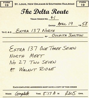
Example Form 19, St. Louis Southern Model Railroad
Most model railroad train orders are given verbally one at a time, and usually are repeated back by the train conductor (hopefully close to the original train order), since model railroad train order operators are fairly rare. Modelers usually don’t number or write down train orders, or follow the communications protocol described above.
Train Orders
The most common uses for train orders are to run extra trains and override superiority rules for regular (scheduled) trains. A dispatcher may decide to hold a train, give rights over another train, or arrange a meet.
Extra trains
are identified by the word “extra”, the engine number of the lead unit, and the direction (“Extra 1374 West”). Extras with foreign power typically include the road (“Extra MP 352 South”). Modern railroading designates regularly-run extras with symbols, the letters and numbers indicating origin, destination, type of train, and direction. Most modelers find it useful to distinguish Passenger Extras from (Freight) Extras.
A turn is a way freight that runs down the line and then returns to its starting point. Frequently run turns usually are named by the location where it reverses direction for the return trip. Many railroads have turns that run daily to ensure consistent service to all of the industries along that route. Other common turns include a mine run or a branch line train. The out-and-back route allows for easier switching, by only switching trailing point spurs in each direction.
Locals
operate like turns, except over a shorter range and usually for specific major customers. This allows them to switch industries multiple times per day. Locals receive cuts of cars from through and way freights to be spotted at the local industries.
Orders for extras and turns do not give them any superiority; they are completely responsible for clearing all regular trains and must take the siding at their destination. When two extras meet, the one of inferior direction takes the siding. Unless your model railroad has functioning Rule 261 block signals, the dispatcher will need to issue orders for meets of extras since their crews won’t know the locations of the other trains (and no, you can’t take a walk down the aisle and check out the situation!).
Rights
, along with permission to meet or pass, may be given to inferior trains by train order. Usually you’ll want to give rights, since it allows the rules of superiority to work out any other issues. The crew operating the extra will need a complete timetable of regular trains however to figure out the potential conflicting traffic.
Wait
and hold orders give the dispatcher time to work out problems.
You annul hold orders, and can annul portions of a regular (scheduled) train: “Lone Star Chief is annulled Texarkana to Dallas”. Modern railroading uses “cancel” instead of “annul”.
An advantage of extras over regular trains is that they can move at the speed of the crew’s skill. On the other hand, they don’t have the incentive (of regular trains working against the clock) to complete work quickly. Since orders need to be issued for all meets and passes, extras may have difficulty moving when regular traffic is heavy.
But how is the dispatcher able to make these decisions? It’s because he knows where the trains are located. His primary tool is the train sheet, where the time specific trains were at specific locations is recorded. The time and location is a train’s OS, because it was recorded by the dispatcher “on sheet“.
Train Sheet
The NorthStar 99 clinic, and the expanded version of this article, will include a sample train sheet and a simple demonstration on how the dispatcher uses it.
Realistic Operation, Phase 7
You need a communications system to add a dispatcher. This either takes the form of a telephone or radio system. Direct radio communication on the prototype between train crews and dispatchers has existed since the mid-1950’s (although the early systems didn’t work all that well), and modern railroading makes extensive use of radio communications. Before the radio era, crews could only communicate with the dispatcher by stopping at a location with a phone box or an operator. Crews also received a one-way communication from the dispatcher by picking up or hooping train orders.
Many model operators have standardized on 5-channel Maxon or Radio Shack FM headset radios (21-407). This is a simple system to install since you just purchase the radios and use them. The radio option is useful even if you are modeling a pre-radio era and you want to avoid the hassles of wiring a phone system. Either tell crews they can only call in when at a phone or location with an operator, or take the radios off the operators and hang them next to the stations —the radio there can only be used when a crew is at that station.
Establish a communications protocol. The dispatcher has top priority on the communications channel, followed by towermen and yardmasters, with train crews at the lowest priority. Apply the rule “listen before talking“. Higher-level communications have priority over lower ones. Communications need to begin with the name of the called operator followed by the caller’s identification: “Dispatch, this is Glenwood tower” or “Extra 142 South, this is dispatcher”.
Timetable and Train Order Dispatching
(T&TO) is very paper-intensive on real railroads. Most model railroads dispense with the paperwork and treat verbal train orders as if they were on paper. Usually the only paper document left is the train sheet, which the dispatcher still needs to keep track of, and plan, the action.
Towermen and station operators call in trains passing their location to the dispatcher, who records that information on the train sheet. On most model railroads, the train crew call in their position when passing towers and stations, simulating the report of a tower or station operator: “Dispatch, OS Extra 89 South at Hoxie Tower”.
Using the communications system, and receiving and recording the train locations, the dispatcher may now issue train orders for movements not on the timetable to enhance and streamline operations.
With real T&TO operation, train crews only got orders at towers and stations. Since it is unlikely your model railroad will have towermen and station operators, train crews will likely get their orders directly from the dispatcher. The train crews need to operate as if they received those orders at a tower or station, and may have to align switches for meets and passes as ordered by the dispatcher, tasks performed on real railroads by the towermen.
An order for an extra train gives the engine number and the points between which it runs. Extra 142 South was created by the dispatcher with “Eng 142 run Extra Ouchita Junction to Alexandra”.
A order for a turn may use its name instead of the engine number, and includes the phrases “turn” and “and return” as in “Glenwood Turn run Extra El Dorado to Glenwood and return”.
Orders setting up meets between trains moving in opposite directions are straightforward: “Passenger Extra 137 North meet Extra 142 South at Pine Bluff”. The inferior train would take the siding at Pine Bluff.
An inferior train may pass a superior train moving in the same direction by order: “Passenger Extra 137 North pass No. 36 at Walnut Ridge”. Number 36 would take the siding and allow Extra 137 North to pass on the main track.
A variation is the pass when overtaken order: “Extra 142 South pass No. 27 when overtaken” has No. 27 taking the next siding after Extra 142 South catches up with it.
When traffic gets tough, a wait order may help to sort things out: “Glenwood Turn wait at Camden until 10:42am”. And when things get really bad, roll out the hold orders: “Hold Extra 142 South” or “Hold all northbound trains” or (when disaster strikes) “Hold all trains”. Resume operations by annulling the hold order, or releasing specific trains: “Extra 142 South may go”.
Additional clarifications may help some crews: “Extra 87 West take siding and meet No. 14 at Magnolia” or “Extra 163 South hold main and meet Camden Turn at Smackover”.
Track Warrants
The simplifications to T&TO mentioned in the previous section to make the system easier to use on model railroads actually results in dispatching close to current standard procedures for real railroads (for those locations that don’t have CTC installed). Track warrants, transmitted by radio from the dispatcher directly to the train crew, give permission to proceed to a specific station or location. If modeling modern railroading (after the mid-1970s), simplified track warrant radio procedures would be used instead of T&TO.
The dispatcher and train conductors have pads of identical track warrant forms. Using radio, the dispatcher transmits the warrant to the conductor, spelling out station names and numbers. The conductor fills in the form and repeats it back at the end.
Model warrant number one is issued at the start of a new operating session. Communications are similar to model railroad train orders, except the process is streamlined by using check boxes. After contacting the train’s conductor by radio “Train 161 North, advise when you are clear to copy a track warrant”, the dispatcher issues the warrant: “Track warrant number fourteen to Conductor RE Lake on Train Hundred and Sixty-One North, April Nineteen, Nineteen Fifty-Eight at El Dorado Yard.” “Check box number two. Proceed from El Dorado to Smackover.” “Check box number four. Hold main track at Smackover.” After the crew correctly reads back the warrant, the dispatcher puts it into effect with “Track warrant number fourteen to Train Hundred and Sixty-One North is OK at 8:30 am, RWS.” “RWS” is the dispatcher’s initials. When the train arrives, the conductor will report “clear” and the time, which is recorded by the dispatcher. The train can’t move until it receives a new warrant.
Waybills and Car Movement
Most railroads depend on the movement of freight for their revenue. Railroads use waybills to track each car and its shipment along with the shipper, the consignee (or destination customer), any special handling, and information important to determine the freight charges. The original waybill travels with the car in the custody of the conductor. As the car moves between roads, a junction stamp is applied to the waybill documenting the actual route of the car. The destination road collects the freight charges and uses the waybill to determine the share each of the handling roads receives.
Online shippers receive an empty car from the home road. Loads move from the shipper to the consignee. If the destination is somewhere else on the home road, the car may picked up by a local freight, taken to the local yard near the shipper, placed in a through freight headed for a local yard near the destination, and placed in another local freight there which delivers the car at the destination. If the final destination is on another railroad, the car is moved to, and delivered at, an interchange with a connecting railroad that can take it to the consignee’s location, or at least move it in their direction.
Home road empty cars go to an empty-car storage track in a home road yard. Foreign road empty cars return to their home road empty, unless a load moving in that direction can be found. Interchange tracks with connecting railroads are required to model this critical aspect of real railroading.
Unit trains
are examples of captive equipment, which travel between two locations in dedicated service. LCL (less than carload) traffic was once handled by way cars, which were run down the line stopping at freight houses to load and unload.
Model railroad waybills order the movement of cars, at a minimum indicating the destination of the car. Advanced model waybill systems indicate the location of the car, if it is ready to roll, its destination, and if it is a load or empty. This information then drives how trains are blocked in the yards, the setouts of blocks along the line, and the switching work performed by the way freights and locals.
Real railroad waybills are shipper oriented. A shipper orders a car, specifies when it is to be delivered, when it is to be picked up, and the destination. Some model waybill systems, such as most computer generated switch lists, are train oriented. If the train doesn’t run, the car doesn’t move, and subsequent operations usually are impacted.
Car Forwarding Systems
Each model car forwarding system has advantages and trade-offs. The amount of detail and information available to, and managed by, the crews increases with the complexity of the system.
The simplest system is Jim Hediger’s wheel report, described in the May 1984 Model Railroader, which we used to structure one form of substitution switching in Phase 5 of our Operations Development Plan. Crews setout a specific number of cars by type at each town. Each train crew selects cars and car spots with the same number of pickups occurring for each setout.
Basic switch lists
build on the wheel report by providing specific spotting locations for designated car types. The next step up adds reporting marks and special handling instructions.
Computer generated switch lists
use tables of the cars on layout, their type, and potential delivery locations. The system generates moves of appropriate cars to appropriate destinations, attempting to avoid repetitious activity. Issues with some of the software in this category includes a) order on the switch list isn’t the order the cars are sitting in the yard, b) cars can only move when the computer list says they can, and c) misrouted or lost cars usually become a serious problem. The most well known computer generated car movement program is Albion Software’s ShipIt! http://www.penn.com/albion/html/ship_it_.html. ShipIt! generates the switch lists before an operating session and assumes the cars will be moved as indicated on the switch list. Remember, real railroads use computer generated switch lists for blocking and switching, so this type of system can “look and feel” the closest to real modern railroading.
Tab on car
systems use colored and coded roof tabs, tacks or stickers. Typically the color indicates the originating yard/area blocking and the code letters/numbers indicate the spotting destination. Setup can take more time than card or software based systems, due to the need to make the custom tabs. Many modelers also have cosmetic issues with this approach – they don’t like the brightly color tabs on top of equipment. On the other hand, it eliminates the need to carry around waybill or switchlist paperwork.
Early car card systems were developed by Doug Smith and first described in the December 1961 Model Railroader. Steve King and Allen McClelland made some improvements to the system which was described in the February 1978 Railroad Model Craftsman. The Midwest Railroad Modelers streamlined blocking trains with a TIBS code in the July 1987 Model Railroader. Car card methods simulate prototype car movements well, but have difficulty simulating flow frequency for high volume industries.
In a preset car card system, like that of Gerald Dyrar, each car has a corresponding 3″x5″ index card with a list of logical destinations. A paper clip is moved down the list, indicating the next movement for that car.
Car card and waybill
systems use a 3″x5″ index card with the card information, and a transparent pocket for a two-sided waybill. With no waybill, a “return when empty” destination appears through the clear pocket. A “freight agent” in the yard adds a waybill to the car card. Additional cards may be added to the pocket with special handling instructions. The crew may turn the waybill once it is delivered to its destination, preparing it for its next move.
Substantial enhancements were made by the Don McFall car card and waybill system (described in the next section). These included reduction in the size of the paperwork to be carried by the crew, more versatility in routing, and options for special operations.
One big advantage of car card systems is that routing errors are self-correcting. If a car is left at the wrong place, the next local switching that location will read the card or waybill and forward the car to its correct destination.
When creating waybill or switchlist destinations, you know the industries that are on your model railroad, but how do you figure out reasonable destinations “off the layout” for interchange traffic? One solution is Chris Butt’s industry database which is available online at http://members.aol.com/Opsigmem/industry.html, courtesy of the NMRA Operations SIG. It lists over 6,200 real-world online shippers.
A related issue is that you will want to make sure that the commodity being shipped matches the car type. This will require research on which commodities are shipped in what kind of cars in your area. This is an era-specific issue as well. For instance, Kaolin clay is now shipped as slurry in special tank cars. Forty years ago it was shipped as a powder in boxcars with roof hatches.
The various alternate waybill and switch list car forwarding systems will be discussed in greater detail at the NorthStar 99 clinic, and in the expanded version of this article.
Realistic Operation, Phase 8
The most popular model railroad waybill system is Don McFall’s Car Cards.
The car cards are 2″x4″ and have the car information on the top and a pocket on the bottom. The car information includes the road name, number, and AAR car type. A waybill slides into the pocket. The waybill covers a “When empty, return car to:” area on the card car but does not cover the car information at the top of the card. The “when empty” area provides a routing for a car without a waybill in the pocket.
Each 2″x3″ waybill has four car movements or cycles. Waybills have a box for the AAR car type. Each of the four movements has a “To:”, “From:”, and “Contents” area. The “To:” and “From:” portions each list the destination (town) and receiver (industry). The size of the waybill and pocket is designed so that only one movement shows at a time.
Each town and yard has a waybill box on the front of the layout’s fascia, with a compartment labeled for each track. When a car is setout on a track, the corresponding car card is placed in the compartment for that track. A narrow sorting shelf near the waybill box is useful at yards and heavily industrialized towns.
Operators don’t turn or modify the waybills, they just follow the instructions on the waybill and leave it in the car card. Only the Superintendent, usually between operating sessions, turns waybills.
Special order forms may also be placed in a waybill pocket. The Empty Car Order simulates a shipper requesting an empty car. In addition to the location needing the car, the order includes the required car type and any special instructions. A yardmaster receives the empty car order, locates an appropriate empty (usually abbreviated “MTY”) car in his yard, places the empty car order form in the car card pocket, and places the car in a train headed in that direction for setout. The Superintendent, between sessions, replaces the empty car order form with a waybill to route that car in the next session. The Old Line Graphics version of this form has a Special Waybill form printed on the back side, which may be used to write those next moves.
Blocks of cars are moved with Mine Block and Multi-Car Block cards. Individual car cards (the part with pockets) aren’t used since the block cards have the road and number of the first and last card in the block, and how many cars are part of that block. The cars stay together and move as a block. The cards list the destination for delivery. Mine block cards add the type of coal and where it is to be washed and weighed. Multi-car block cars add the type of load.
A Train Order card may be used to create an extra or turn. The train order car would include the train number, engine assignment, origin and destination, and special instructions. Extra 142 South could be created by the dispatcher with this printed version of the “Eng 142 run Extra Ouchita Junction to Alexandra” order. The yardmaster tacks on a caboose, drops the power on the train, and hands the train order card, with the car cards of the cars in the train, to the crew.
A train instruction card may still used to list the station stops, and any special information the crew may require, for regular (scheduled) trains.
The train crew should always check their cards before leaving the yard, and during a run, to ensure they have the right cars and to plan their switching moves. Turns typically switch trailing point sidings on the way out, and handle the remaining sidings on the return.
A rubber band, spring clip, clear pocket protector, or convention name badge holder may be used to keep the train instructions and car cards together. The pocket-style bundling tends to be less damaging to the cards than spring clips.
When creating the waybills, keep in mind that prototype car service rules state you should load a foreign-road car if doing so will send it back in the direction of its home road. If you don’t have a load, the car is returned empty by the same route it came.
Two companies are able to help you set up McFall car cards and waybills. Old Line Graphics, 1604 Woodwell Road, Silver Spring, MD 20906 offers all of the forms as preprinted pads. They have a starter kit available for $16 (Jan 98 price). Car cards, waybills, and empty card orders are $1.75 per pad of 50. Train orders, mine block, multi-card block, and bad orders are $1.25 per pad of 50. Shipping on all orders is $4 per order.
MiTrains
and Waybills for Operations computer software, available from Shenandoah Software, Post Office Box 130, Alachua, Florida 32616, (904) 462-5678, http://members.aol.com/Shenware/waybills.html, prints the card cards and waybills. Shenware’s program integrates Chris Butt’s industry database of over 6,200 online industries in the US and Canada. The $49.95 software prints waybills on inkjet and laser printer business card sheets available at office supply stores or on plain paper. A demo version of the software is available on their website. It was recently brought to my attention that Albion software also makes a car card version of their software, ShipIt! Car Cards (http://www.penn.com/albion/html/car_cards.html).
Passenger Train Switching
Don’t forget that passenger trains switch too. Cars were regularly added and removed from trains to meet the passenger traffic needs, or to adjust the mix of accommodations for various segments of a train’s run. Passenger trains commonly carried mail and express packages using specialized head-end and express equipment. Adding mail, REA, express, and passenger equipment preparation facilities to your layout can open up all sorts of new operation possibilities. Car card and waybill, or switchlist, systems may be applied to passenger car-forwarding operations as well.
Centralized Traffic Control
The dispatcher operates the CTC machine. It directly controls signals and switches along its portion of the line. The dispatcher plans moves based on indicator lights showing the positions of trains. Lineside signals are normally red unless set to green by the dispatcher. The CTC machine will prevent the dispatcher from setting a signal to green, or throwing a switch, if it is inappropriate to do so. Signals usually operate as APB (absolute permissive block), so yellow indications appear automatically and opposing moves see solid red. Trains operate following signal indications. Authority by timetable disappears along with most train orders. Only those very few movements that cannot be handled by CTC receive train orders.
Adding CTC is a very serious (time and money) investment. At a minimum it requires track detection, powered switches, and operating signals managed by a computer running a program custom to the railroad connected to a custom CTC board or display system. Real Class 1 railroads introduced CTC in the 1930’s, and have steadily evolved the concept into the computer dispatch control centers of today’s railroads. Since crews need to see the indication of every signal, visibility of the signals becomes an important layout design consideration. CTC is used by the prototype to increase their traffic volume on a route, the same will happen on a model railroad using CTC. Wider aisles, and additional staging, will be required as a result. CTC is for modelers interested in realistically running heavy volumes of mainline traffic.
Operations Development Plan Summary
As we covered the various topics and considerations when designing model railroad operations, we also created a corresponding operations development plan. This eight-step plan will help you to start operating now, and provides easy transitions into other areas of model railroad operation.
- Scale speed
- running
- Name
- everything
- Get the railroad to work mechanically and electrically
- Create a Train Service Plan and Sequence Timetable
- Start Substitution Switching
- Timetable Operations
- by fast clock
- Train Orders
- by dispatcher
- Freight car waybill system
An expanded version of this article is available as a handout at my NorthStar 99 clinic presentation. The expanded version is also available in the online library at the Gateway Division NMRA web site, https://www.gatewaynmra.org, along with numerous sample forms and documents you may use for model railroad operations. The author reserves all commercial publication rights to this clinic.
Recommended Reading
Armstrong, John “The Railroad: What It Is, What It Does”, Simmons-Boardman Books, ISBN 0-911382-04-6. Read how the real railroads work from a book used to train real railroaders.
Armstrong, John “Track Planning for Realistic Operation”, Kalmbach Books. Prototype and model track design considerations and fundamentals of real railroad operations in the steam era. A “must have” book.
Chubb, Bruce “How to Operate Your Model Railroad”, Kalmbach Books, ISBN 0-89024-528-2. Out of print, but an excellent reference if you can find a copy.
Mallery, Paul “Operation Handbook for Model Railroads”, Carstens Publications, ISBN 911868-74-7. You’ll want this book.
Villaret, Eugene “Realistic Revenue Operations”, Greenberg Publishing, ISBN 0-89778-000-0. Describes how to use an early car card system.
Alcock, Bruce & Raskob, Michael “Passenger Train Operations on the Chesapeake System”, Model Railroader, August 1996, p58-63. How to design interesting passenger train operations.
Barrow, David “How to Operate Your Layout”, Model Railroader, October 1995, p104-109. Designing operations for an MR project layout.
Barrow, David “Operating the South Plains District”, Model Railroader, December 1996, p100-105. Applying basic operation concepts and McFall car cards to another MR project layout.
Barrow, David “Yard Throats for Operation”, Model Railroad Planning 1997, p84-85. Good ideas for yard design.
Birsa, Joe “Telephones on the Huntingdon Northern”, Railroad Model Craftsman, April 1999, p78-82. How to construct a steam-era phone system.
Boelter, Bob “Organize Your Card Cards”, Model Railroader, December 1996, p139. Using brochure holders to make waybill boxes, and convention name badge holders for car card carriers.
Darnaby, Bill “Card-Order Operation for Passenger Trains”, Model Railroader, October 1993, p74-77. Applying freight-car waybill concepts to passenger traffic.
Darnaby, Bill “Designing a Timetable for the Maumee Route”, Model Railroader, January 1993, p80-87. Excellent description of designing T&TO operations on a freelance railroad.
Darnaby, Bill “The Maumee Turns a Mike”, Model Railroader, July 1996, p94-97. How to model and operate a steam servicing facility.
Dolkos, Paul “The Joys of Junctions”, Model Railroad Planning 1995, p10-15. Describes and illustrates the various kinds of junctions and their operation.
Geletzke, Charles “Name that Track, Principles of Prototype Track Identification”, Model Railroader, June 1994, p94-97. How the prototype names and numbers tracks.
Gruber, Bill “Enhancing Operations with Procedures Manuals”, Railroad Model Craftsman, January 1992, p72-75. Overview on what should be included for a good model railroad procedures manual.
Gurin, Doug “A Primer on Helix Design”, Model Railroad Planning 1997, p72-77. If you are going to build a helix, read this article first on how to do it right.
Hediger, Jim “Railroading Without Derailments”, Model Railroader, May 1996, p80-81. Basic checks for track, turnouts, trucks, and couplers for dependable operation.
Hediger, Jim “Wheel Reports for Easy Operation”, Model Railroader, May 1984, p102-103. A minimal-paperwork operating method.
Hitchcock, Chuck “Santa Fe Passenger Trains on the Argentine Division”, Great Model Railroads 1991, p20-27. Creating intensive passenger train operations based on a prototype. Passenger trains switch too!
Hitchcock, Chuck “Twelve Hours at Argentine”, Model Railroad Planning 1997, p10-17. Forget freight trains! Running and switching passenger trains is where this railroad’s action is at.
Holbrook, Dan “TIBS, the Train and Industry Blocking System”, Model Railroader, July 1987, p91-95. Excellent description of how to use the Smith-King car card and waybill system.
Houghton, Allan “Care and Feeding of the Steam Locomotive”, Model Railroader, July 1995, p68-73. Modeling critical details and structures surrounding a turntable.
King, Steve “Car Cards and Waybills”, Railroad Model Craftsman, February 1978, p68-73. Detailed, step by step explanation on how to use the Doug Smith-Steve King car card and waybill system.
Koester, Tony “Enhanced Car Forwarding on the Midland Road”, Model Railroader, March 1993, p75-81. Very good explanation of how to use the Don McFall car card waybill system.
Koester, Tony “Improved Handling for Empty Freight Cars”, Model Railroader, March 1994, p76-79. Follow-on to the March 93 article, describing empty car handling and explaining car service rules.
Koester, Tony “Operation Brings a Coal Branch to Life”, Model Railroader, November 1998, p82-87. Covers operations on the newest extension to his layout, with samples of the train register, timetable, clearance form, and form 19 used.
Koester, Tony “Midland Road Moves Coal”, Model Railroader, February 1997, p70-79. Discusses design of coal operations, using staging and McFall Mine Block cards.
Koester, Tony “Yard Operations on the Allegheny Midland”, Model Railroad Planning 1996, p10-15. Design considerations and operations in a 1950s-era yard.
Middleton, William “Steam Locomotive Servicing Facilities”, Railroad Model Craftsman, p76-83. How prototype steam servicing works.
Prehoda, Bob “Operating with Train Orders”, Railroad Model Craftsman, June 1999, p69-74. Designing T&TO operations using real train orders, with examples of the paperwork and a description of how it is applied.
Providenza, Jim “Operating Night on the Santa Cruz Northern”, Model Railroader, May 1996, p72-79. Track warrant operations on a freelance railroad.
Schuchmann, Walt “Computer Waybill Operation”, Model Railroader, November 1989, p114-119. Microsoft BASIC program to randomly select waybills from a previously entered table.
Sebastian-Coleman, George “DCC Buyers Guide”, Model Railroader, June 1999, p62-68.
Senese, Jim “Five Railroads, Four Yards, One City”, Model Railroad Planning 1999, p18-25. Modeling the major Kansas City yards and their interactions.
Sperandeo, Andy “Tab-on-car Operation”, Model Railroader, December 1981, p84-88. Describes how to design and use the tab-on-car car forwarding system.
Strang, Lionel “Evolving Paint Schemes on the Allegheny & Lackawana Southern”, Model Railroader, November 1996, p78-83. Discusses how to develop a believable paint scheme for a free-lance model railroad.
Williams, Ron “Track Warrant Control on the CATS”, Model Railroader, August 1992, p68-71. How to use track warrant style dispatching on a model railroad with step-by-step example.
Wilson, Jeff “Modeling from a Timesheet”, Model Railroad Planning 1999, p10-17. A model railroad of a junction, modeling the prototype traffic at that spot.
Lake, Richard “Series on Freight Yard Operations”, https://www.gatewaynmra.org/frt-yard.htm
O’Brien, Mike “Layout Design Primer”
Schumacher, Richard “Computers and Model Railroading”, https://www.gatewaynmra.org/computer.htm
Gateway Division on-line library, Operations articles and forms, https://www.gatewaynmra.org/operate.htm
Layout Design SIG, http://www.ldsig.org/
Operations SIG, http://members.aol.com/Opsigmem/index.html
Operations SIG Industry Database, http://members.aol.com/Opsigmem/industry.html
Join the NMRA Operations SIG. For only $15/year you get their excellent Quarterly Publication, the Dispatcher’s Office, and information on operations events. Operations SIG, Box 872, Arlington Heights, IL 60006.


